|
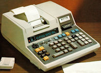
AKA: Canola SV-10, AKA (Label): SV-10, Product number (P/N): SV10 (SV-10),
Keywords/Tags: SV10 (SV-10) | Canola
Date of intro: 1974, Origin: Japan (List), Dimensions: 330x265x115mm, Weight: 4900g,
Power: AC,
Display: Type = Display (VFD) (List), Digits = 12+1,
Keyboard: Reed-switch, Number of keys: 41, #Key-Black: 5, #Key-Blue: 5, #Key-Grey: 19, #Key-White: 8, #Key-Yellow: 4,
Decimal switch: [0-1-2-3-4-6-F-+], Round switch: [(ArrowUp)-5/4-(ArrowDown)], Miscellaneous switch: [ITEM-OFF-Mn], Indicators: OVF,
Classification: / Desktop with Display+Printer / Multiple-type display,
Featuring: Procent, Programmable,
Related with: CANON_docu: (Broch.) SV10: Der anwenderprogramm...,
Collector value: 8/10,
Info:
Thanks to HESS Duane for following analyzing and pictures (15-may-2017, 03-oct-2017)...
I'm very sure this device is not user programmable. The only programming capability is likely the ROM cartridges you stick in the side.
In this respect, it is like the TX10. Programs must be installed in a ROM cartridge. The ROM "burner" was probably an internal CANON only device.
One wonders how users communicated custom program needs. CANON allowed user programs on other ROM devices, but the user could not program the ROM.
I've seen reference to this, but not how it was communicated. i.e by keypresses, some "language", the user must learn the assembly/microcode of the device?
Probably a list of specs and for a fee CANON would code/debug and burn the ROM.
The display is made of 2 vacuum flourescent display tubes. The 12 digit (13 position) display is a VFD flat/"bathtub" tube.
This tube includes the MINUS/ENT output with 3 symbols in one position:
I - E ... If CANON follows other calcs, the I indicates a value in a memory. The brochure indicates 16 memories standard and is upgradable.
'-' ... means minus
'E' ... likely indicates paused for "entry requried". The brochure keyboard picture implies the [+] & [-]-keys indicates the sign of the entry and simultaneously the "resume" for the paused program.
Just a guess, but the keyboard nomenclature would lead to that conclusion.
The leftmost portion of the display has OVF & PROG NO. OVF, assuredly indicates overflow via a single, somewhat large, red LED behind the display lens.
PROG NO is a single round VFD tube.
The power supply has a transformer and 2 capacitors; the larger with 4 connections on the top.
There is some additional circuitry on the bottom side of of the power supply frame.
Likely the rectification and filter-smoothing of the DC. But would require removal to view it.
The keyboard has the usual magnetic reed switches typical of that era.
The keyboard connects to the PCB via a black vertical connection (pins stick directly upwards) directly in front of the power supply.
The motherboard is a single PCB which extends under the printer and very slightly under the power supply.
The pictures shows the small blue female PCB edge-connector P-ROM socket.
Just below (towards user) is a white rectangle (slightly askew) with predrilled holes and indications of an optional feature. Probably the additional memories the brochure highlights.
Since it is a solder-in (no socket) likely must be factory ordered.
I forgot how the socket was marked but was labelled similar to HD3543 (HITACHI), which is the 28 pin memory chip used in the SX300.
In the SX-300 HD3543 obviously is the memory chip.
Oddly, HITACHI usually labelled memory chips HM and various processors were HD.
Needing 13 pins for address lines & 8 data lines leaves 7 pins for power (at least 2), chip select, read, write; 2 left over.
Maybe the HD indicated a custom chip build. Each chip would store either 100 1-byte program instructions or 10 registers of 14 BCD digits
(10 bytes/register: 14 digits, 2 exponent, mantissa sign, exponent sign).
Each program step is one byte (8 bits) and each data register is ten bytes. The HD3546 was used in the SX320II and is "double density" compared to the HD3543.
CANON often referred to the SX3nn as 16 digit displays but they were 14.
Dedicated positions contained the exponent and sign. However the labelled 16 positions for the display was 14 digits, a decimal point and sign.
The PCB connection for the printer is the blue connector immediately left of the printer.
Referring to the TX10 it might have been a BASIC (CAT basic? CAT was a CANON desktop PC) progammable system.
The left keyboard on the TX10 has alphabet. If you spell out LIST, RUN & .... forget what else (DIR) it will respond like a BASIC command interpreter.
However, there is no real output other than the command is recognized with no program or files showing.
!!! This item is WANTED to join the collection !!!
|
| Item |
